Resistance Barriers
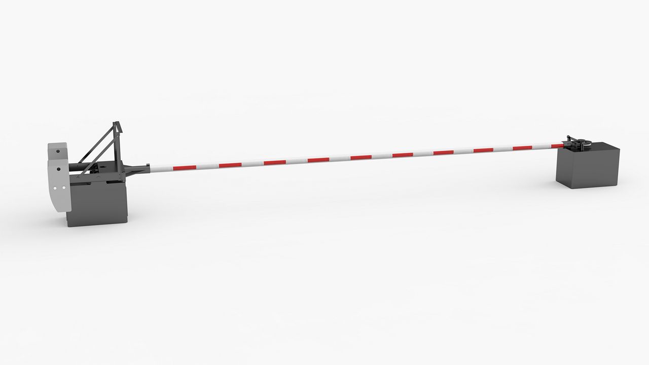
VT-6802HDTR
APPLICATIONS: The barrier shall be explicitly designed for traffic control on movable bridges, as required by AASHTO’s current standard specifications for movable highway bridges, and shall be suitable for similar applications such as railway crossings, Toll lanes, reversible lanes or any application involving traffic lane management.
See below for specification or reach out to your salesperson for more info.

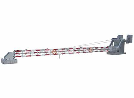
VR-6 VERTICAL RESISTANCE BARRIER
APPLICATIONS: The barrier shall be designed for use as a penetration resistance barrier and shall be suitable for use as a warning barrier for wide spans. The barrier shall be explicitly designed for traffic control on movable bridges, as required by AASHTO’s current Standard Specifications for Movable Highway Bridges, and shall be suitable for similar applications as well.

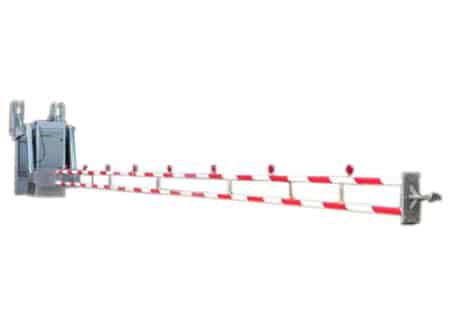
HR-7 HORIZONTAL RESISTANCE BARRIER
APPLICATIONS: The barrier shall be designed for use as a penetration resistance barrier. The barrier shall be explicitly designed for traffic control on movable bridges, HOV and reversible lanes and similar applications.

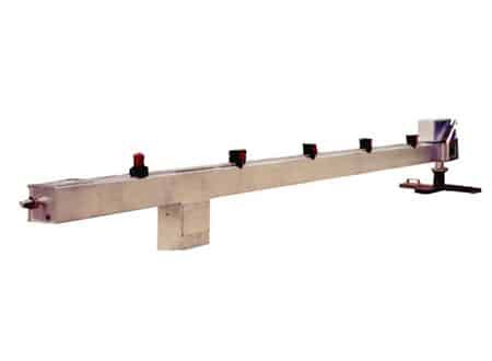
MODEL CR-25 BARRIER
APPLICATIONS: The CR-25 a minimum gate opening of 12 feet (3.7 m) and a maximum of 28 feet (8.5 m). The units are capable of immobilizing a 10,000 lb. (4,535.9 kg) vehicle traveling 18 mph (29.0 km/h). Basic components of the crash beam barriers include the standard vertical to horizontal arm with an energy absorption cable assembly, hinge post, receiver/latch post, cable-reinforced crash beam and automatic controls.